
Selection guide
Automatic vs Semi-Automatic Wire Processing Equipment
Compare automatic lines and semi-automatic wire-processing cells using batch size, changeover, process integration, inspection and labor content.
Read engineering guide →Wire tinning, soldering and welding create different finished connections. Our tinning machines prepare stripped conductor ends, including multi-core and parallel-wire workflows. Soldering stations feed solder or use pulse heat for connectors and flat cable. Ultrasonic metal welders join conductor bundles or terminals; dedicated plastic welders and metal-tube sealing machines are identified separately below. For twisting without tinning, see Twisting, Untwisting & Straightening; for mechanical copper-band splices, see Crimping & Connector Assembly. Send your wire and accepted joint sample so we can demonstrate the required process before you order.
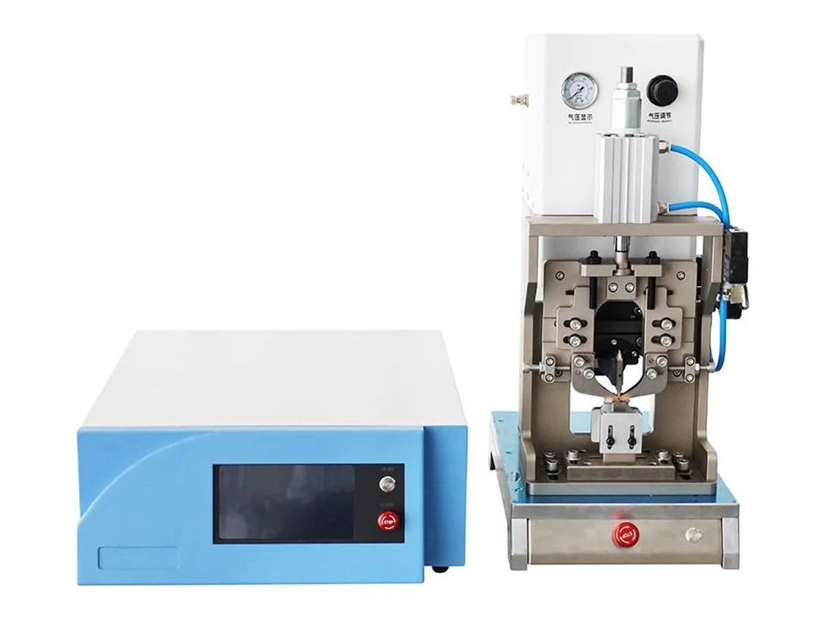
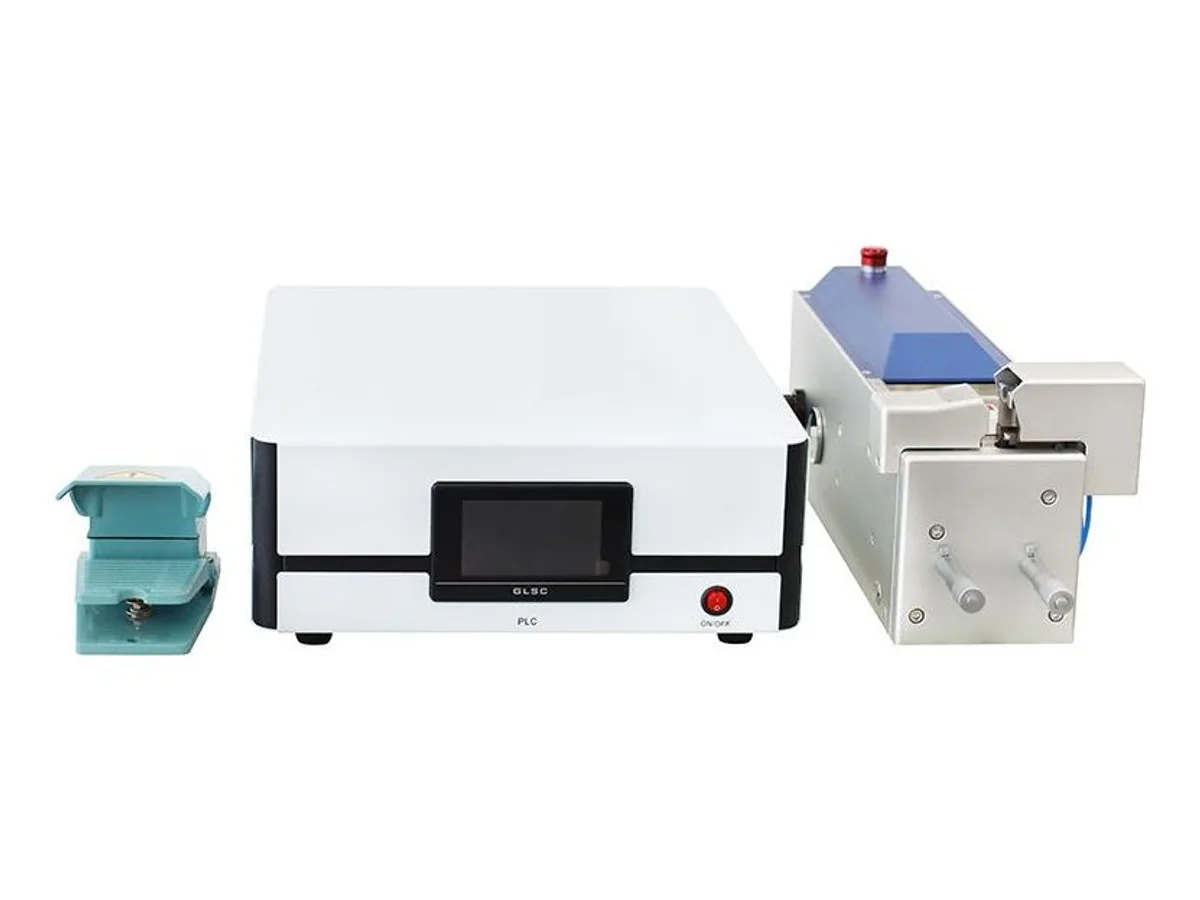
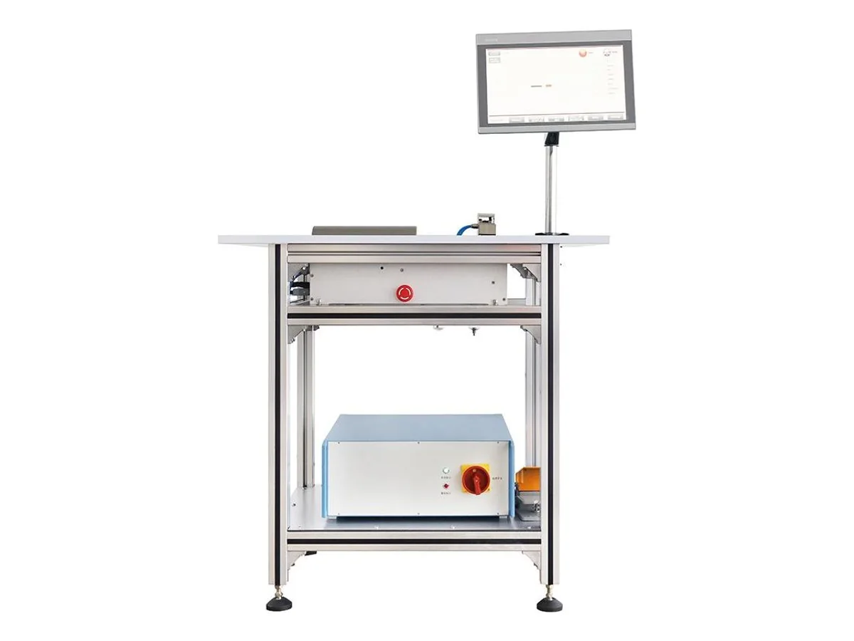
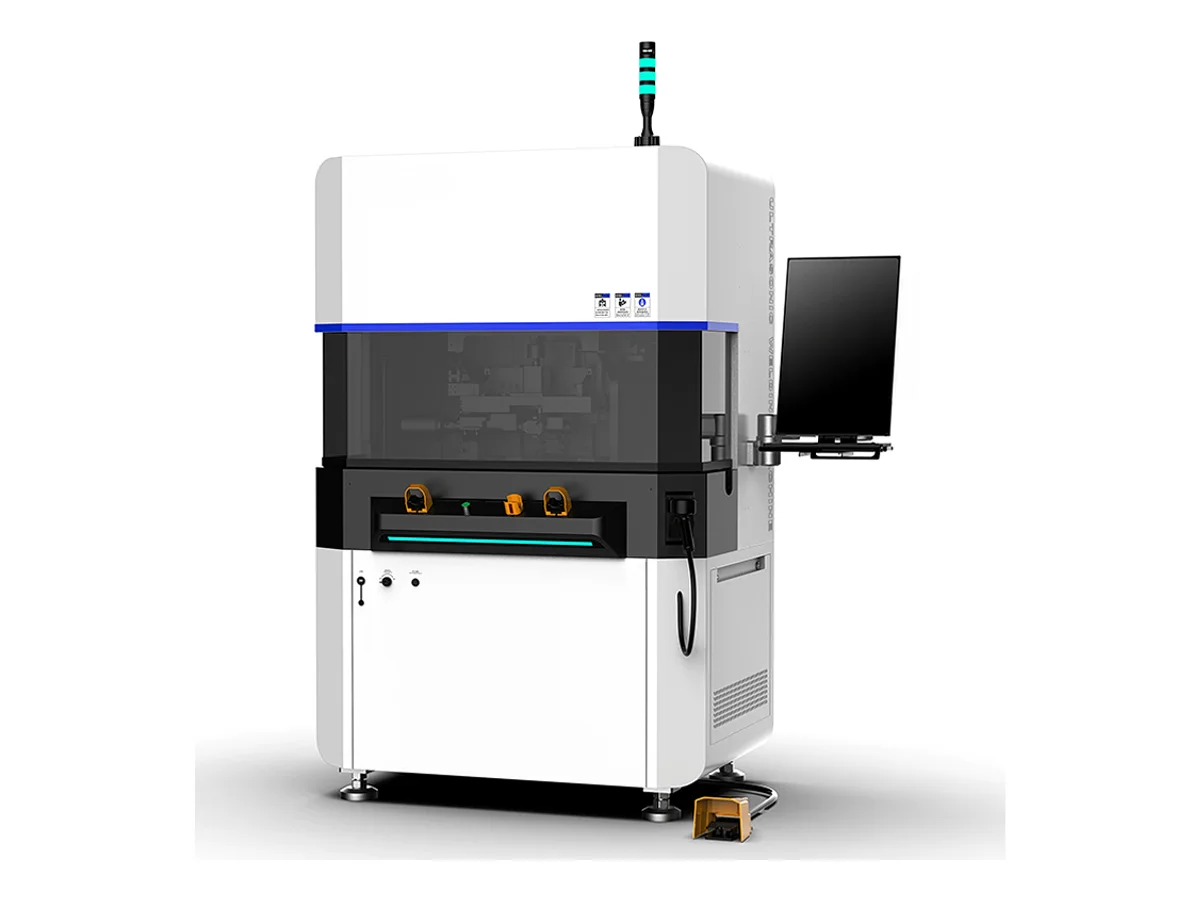
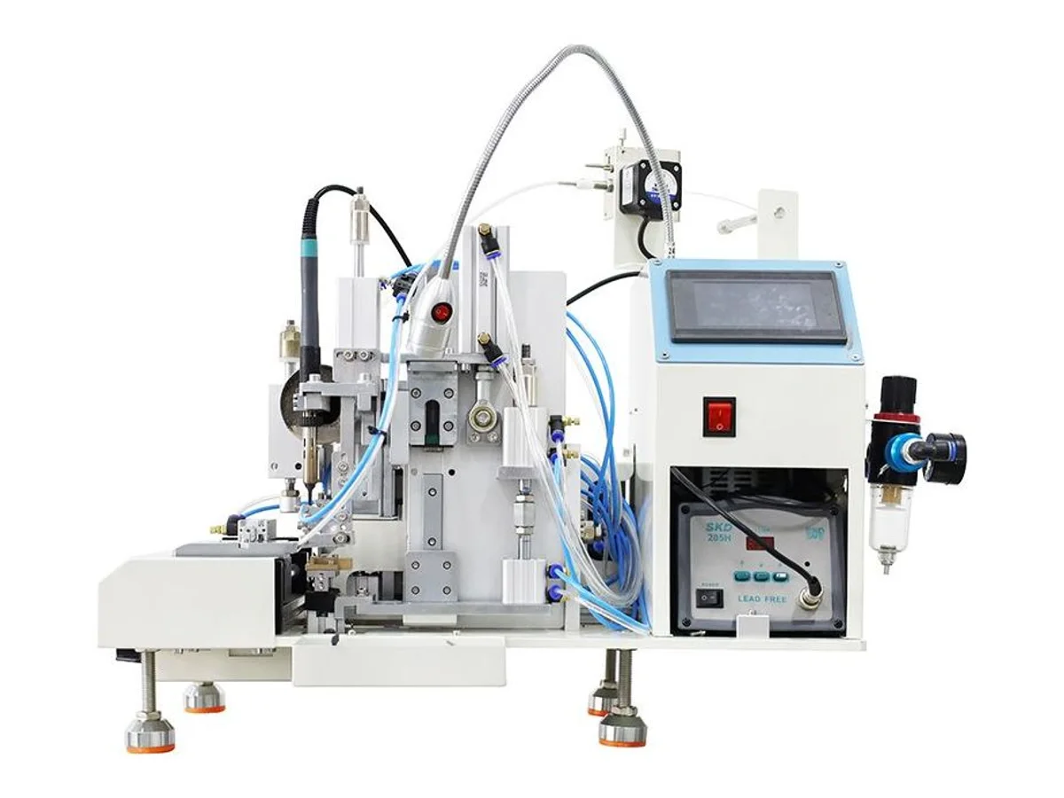
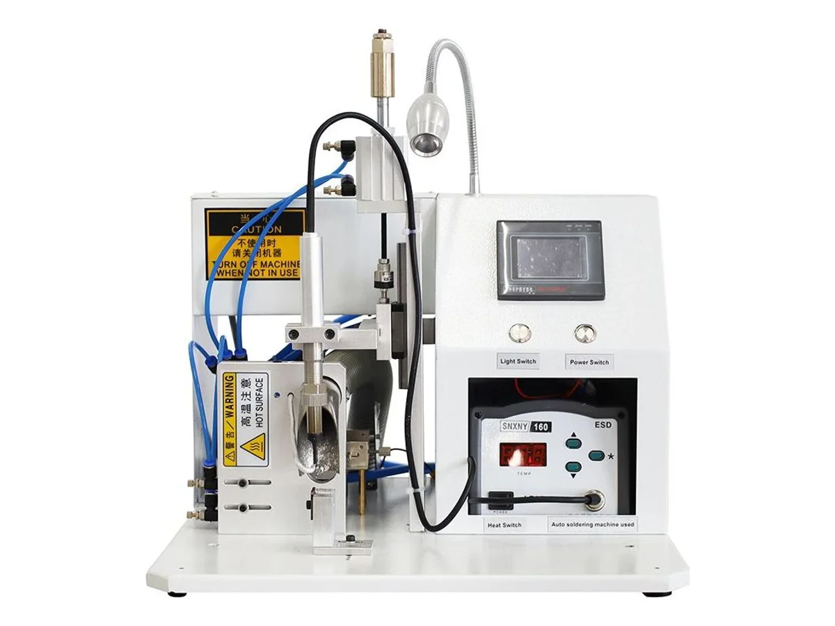
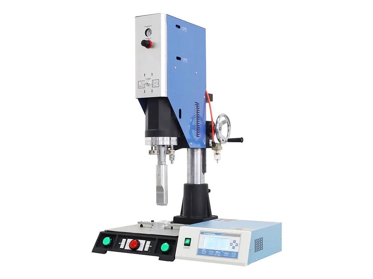
Ultrasonic welding fuses copper strands with 20 kHz vibration and pressure — no solder, no flux, no heat-damaged insulation, and a joint that is metallurgically continuous. It is the modern default for harness splices, and the choice is by cross-section: the WM-711 covers 0.75–20 mm² on 3,000 W with automatic frequency tracking, the WM-717S runs 0.7–30 mm² at 4,800 W, and the WM-718 takes copper splices up to 50 mm² on 5,500 W. For terminals rather than splices, the WM-713 welds at 5,000 W; for plastics, the WM-714 is a 2,000 W full-bridge welder making 1–15 mm spot welds. Copper-band splicing is the mechanical alternative — a band crimped around the bundle: the WM-716 at 4 tons with 1–10 mm reel band, the WM-715 a compact 3-ton benchtop unit. Soldering stays right where a wetted joint is specified: the WM-722 and the WM-712 feed solder automatically (the latter shaped for USB cable at 300–600 pcs/h), and the WM-721 is a hot-bar pulse-heat bonder for FFC, FPC and connectors, 50–600 °C in up to 4 heating stages.
Rate by the total gathered cross-section of the splice, not by the biggest single wire. Three wires of 2.5 mm² joined together present 7.5 mm² to the horn. Published ranges here: 0.75–20 mm² (WM-711, 3,000 W), 0.7–30 mm² (WM-717S, 4,800 W), up to 50 mm² (WM-718, 5,500 W). All run at 20 kHz. One practical detail worth asking about: the WM-711 publishes fully automatic frequency tracking, meaning no retuning after a horn change — that is shift-floor time, not a spec-sheet nicety.
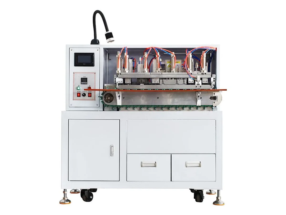
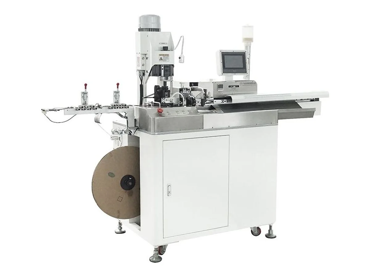
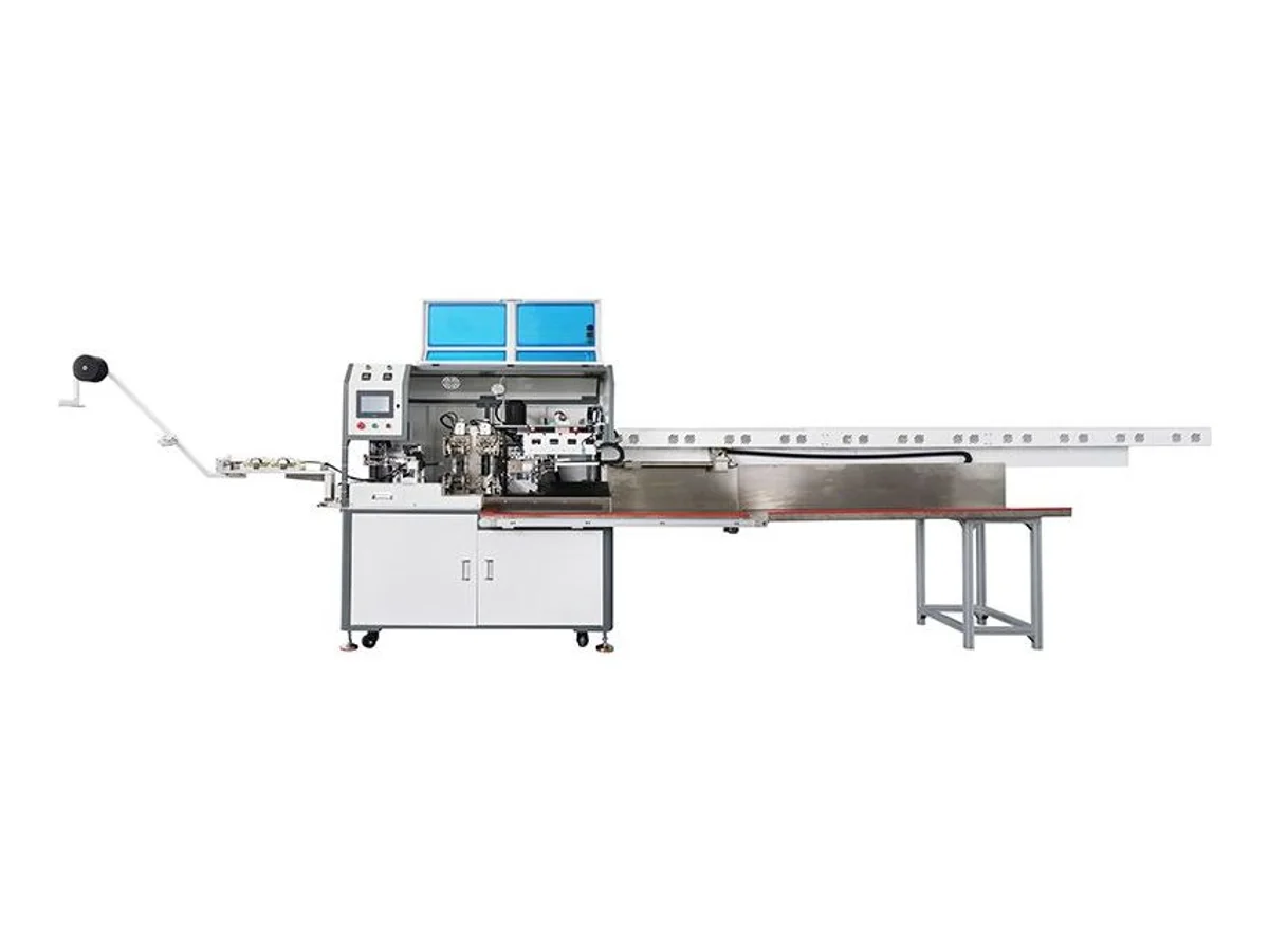
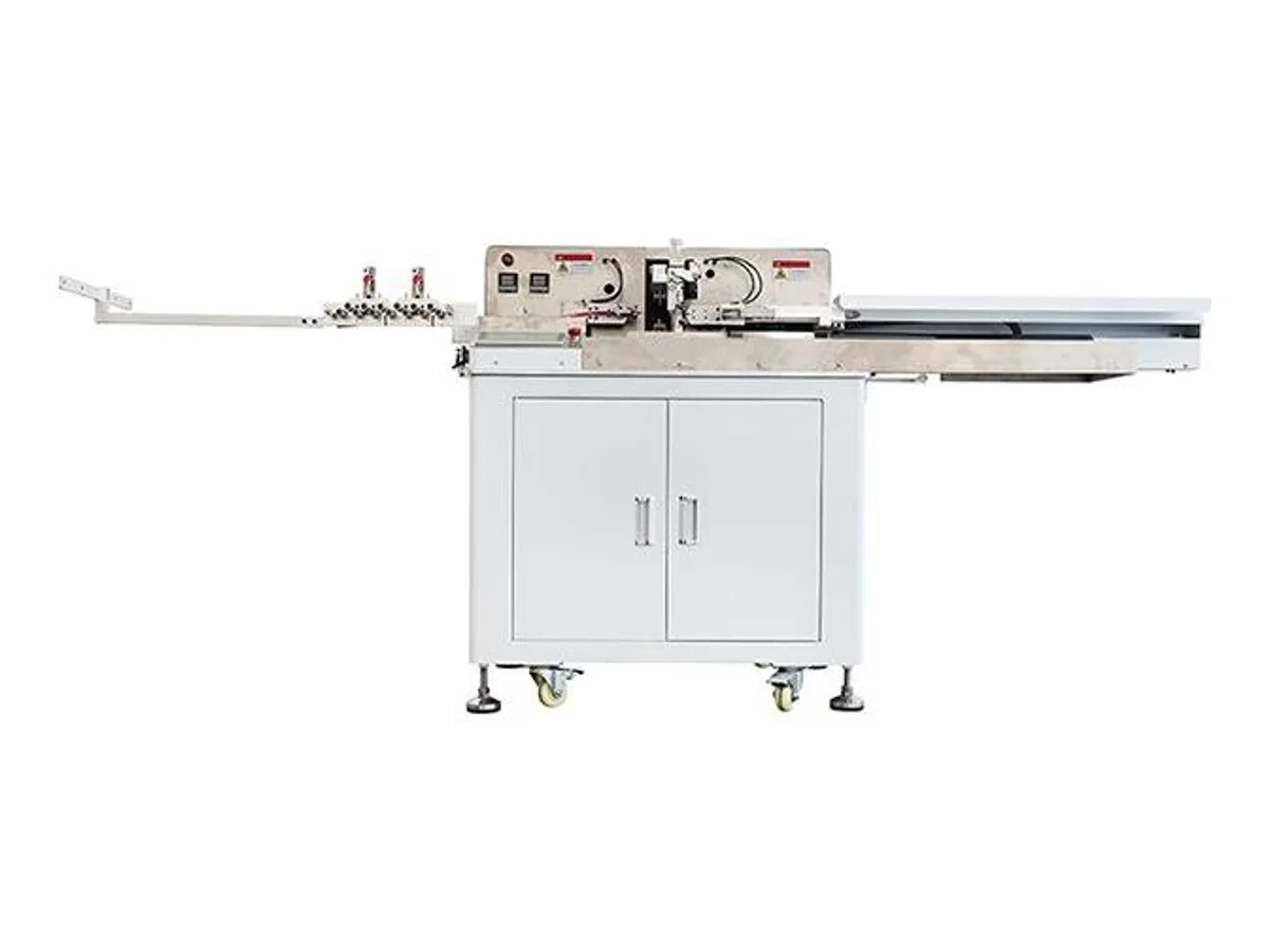
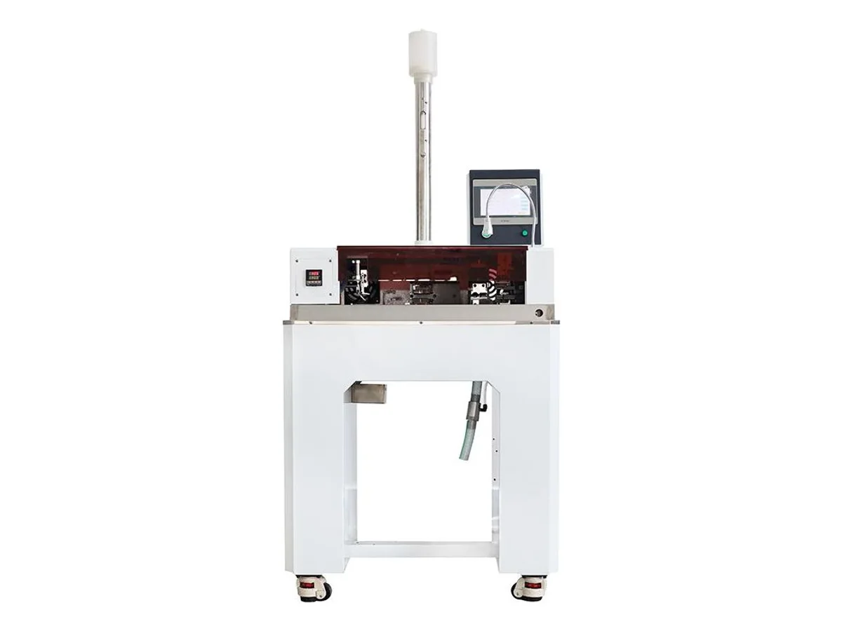
Twisting alone tightens stripped strands so they feed into applicators and solder joints without stray wires. The WM-4720 is the simplest form — pre-stripped wire in, twisted end out, 3,000 pcs/h. Twisted pairs are a different job: the WM-4717 strands 12–36 AWG up to 6 m at 300–7,500 rpm, and the WM-4716 runs six independent axes in parallel, each with its own turn count and direction. Twisting plus tinning is the volume case — the strand is twisted and immediately dipped, so it arrives at the next station solderable: the WM-4715 does it on both ends of sheathed cable Ø3.0–8.0 mm at 2,000–5,000 pcs/h; the WM-4706S handles multicore under Ø8 mm; the WM-4706W runs up to ten independent 18–28 AWG wires side by side; the WM-4710T splits 3-core cable up to 50 mm and strips and tins 2–9 mm on each core.
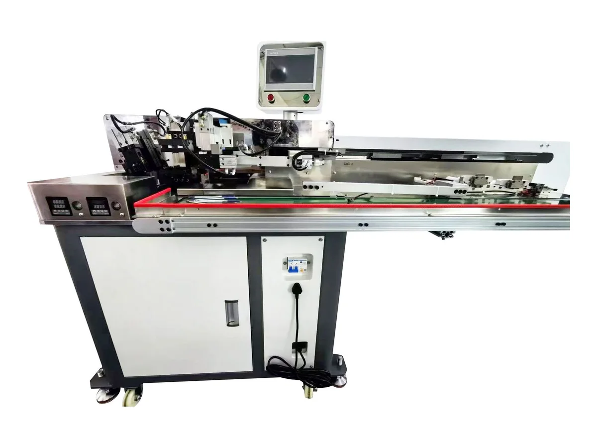
Sheathed cable adds a step before any of this: the jacket has to come off and the cores separate. The WM-4718 does that semi-automatically — jacket stripped from 20 mm up, cores twisted to 15 mm, then dipped at an adjustable depth. The WM-4710T automates the same idea for 3-core round and flat cable (H03VVH2-F, H05WH2-F, H03VV-F, RVV) with 50 mm of core splitting. And if the line must also crimp, the WM-462 strips, tins and crimps five wires with 8–800 mm cut length holding +0.1 mm at L=100 mm.
| Machine | Method | Range | Power | Pick it for |
|---|---|---|---|---|
| WM-711 | Ultrasonic metal welding | 0.75 – 20 mm² gathered | 3,000 W, 20 kHz | Harness splices with auto frequency tracking |
| WM-717S | Ultrasonic splice station | 0.7 – 30 mm² copper bundles | 4,800 W, 20 kHz | The mid-to-large splice range |
| WM-718 | Ultrasonic, high power | Up to 50 mm² copper | 5,500 W, 20 kHz | The largest splices in this category |
| WM-713 | Ultrasonic terminal welding | Terminals | 5,000 W, 20 kHz | Welding terminals rather than splices |
| WM-714 | Ultrasonic plastic welding | Spot weld Ø1 – 15 mm | 2,000 W full bridge | Plastic parts, not copper |
| WM-721 | Hot-bar pulse-heat bonding | FFC, FPC, connectors | 2,000 W, 50–600 °C, 1–4 stages | Flat cable and fine-pitch bonding |
| WM-712 | Soldering with auto solder feed | USB cable assemblies | 300 – 600 pcs/h | Repeatable connector soldering at volume |
| WM-722 | Semi-automatic soldering | — | < 150 W | Bench soldering with automatic feed |
| WM-4715 | Cut, strip, twist & tin both ends | Sheathed Ø3.0–8.0 mm | 2,000–5,000 pcs/h; cut ≤2,000 mm | The volume workhorse of this category |
| WM-4706S | Cut, strip & tin two ends | Multicore < Ø8 mm | Front <60 mm, rear <40 mm strip | Multicore leads, both ends tinned |
| WM-4706W | Multi-wire strip, twist & tin | 18–28 AWG, up to 10 wires | Cut 8–1,000 mm; twist 3–10 mm | Ten thin wires in parallel |
| WM-4710T | 3-core split, strip, twist & tin | 3-core round/flat H03VV-F, RVV | Split ≤50 mm; strip & tin 2–9 mm | Power cord sets from sheathed cable |
| WM-4718 | Jacket strip + core twist & dip | Cores Ø0.8–3.0 mm | Jacket ≥20 mm; twist ≤15 mm | Semi-automatic multi-core prep |
| WM-462 | Strip, tin & crimp, five wires | Ø0.8–3.5 mm | Cut 8–800 mm, +0.1 mm at L=100 | Tinning and crimping on one line |
Choose against the joint specification and conductor materials. Ultrasonic welding joins conductor bundles without adding solder or flux. Soldering remains appropriate where the specification calls for a soldered joint, including suitable connectors and flat cable. We confirm the method, tooling and acceptance results on your actual parts; material combination and joint geometry determine suitability.
By the total gathered cross-section of the splice, not the largest single wire — three 2.5 mm² wires present 7.5 mm² to the horn. Published ranges: 0.75–20 mm² (WM-711), 0.7–30 mm² (WM-717S), up to 50 mm² (WM-718). Send your actual bundle and we weld it before you order.
A thin copper band is fed from a reel, wrapped around the gathered strands and crimped at 3–4 tons, mechanically locking the splice. It is used where ultrasonic is not available or not accepted, and where the joint will be insulated afterwards. The WM-716 crimps at 4 tons with 1–10 mm band; the WM-715 is a compact 3-ton benchtop unit. The dedicated presses are in Crimping & Connector Assembly.
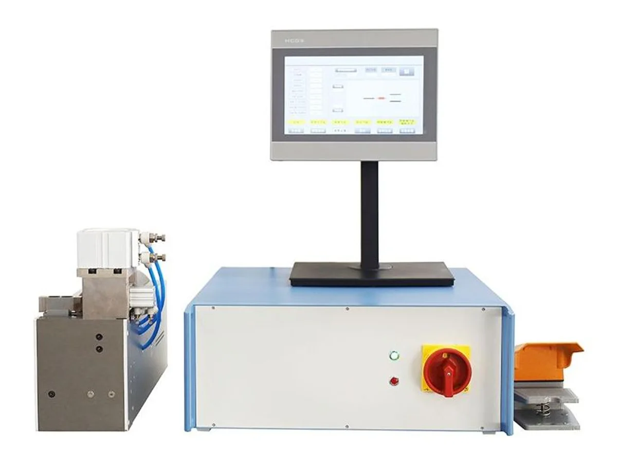
The WM-721 presses a heated bar across the joint and pulse-heats it to a programmed profile — 50 to 600 °C in up to 4 stages. It applies a controlled heat-and-pressure cycle across the contacts of an FFC, FPC or fine-pitch connector, rather than working contact by contact with an iron. We verify the finished joints on your parts; a programmed cycle alone does not guarantee identical results at every contact.
Stripped strands flare. Flared strands cause stray-strand shorts at solder joints and misfeeds in crimp applicators, and hand-twisting cannot hold consistency over thousands of pieces. A machine twist gives every end the same lay — and on the tinning models the twisted end goes straight into the solder pot before it can relax.
Do not assume that pre-tinning is required or acceptable before crimping. Solder-coated strands can deform under sustained clamping pressure and affect connection stability. Follow the terminal application specification for conductor preparation, including whether twisting is allowed. Tinning is used for specified soldered connections; screw-terminal use also depends on the terminal specification. If your process calls for end twisting without tinning, compare the WM-4720.
Strand twisting tightens the loose strands of one stripped conductor end — a few millimetres of work at the wire tip. Twisted-pair stranding twists two or more separate insulated wires around each other along their whole length, for noise rejection. Different machines: the WM-4720 for the first, the WM-4717 and six-axis WM-4716 for the second. See our twisting, untwisting and straightening machines for dedicated stations.
Yes. The WM-4715 cuts, strips both ends and tins them on sheathed cable Ø3.0–8.0 mm at 2,000–5,000 pcs/h. The WM-4710T does it for 3-core round and flat cable with up to 50 mm of core splitting. The WM-4718 is the semi-automatic version when volumes do not justify a full line.
For splices: the wires being joined (count and mm² each), so we can total the gathered section, plus target cycles per hour. For soldering: the connector or assembly, solder specification and joint count per piece. Then courier samples — we weld or solder your own parts on the machine, on camera.
Engineering guidance for choosing this process and correcting the defects that affect finished-wire quality.
Selection guide
Compare automatic lines and semi-automatic wire-processing cells using batch size, changeover, process integration, inspection and labor content.
Read engineering guide →Troubleshooting guide
Diagnose poor solder wetting, excessive wicking, solder bridges, uneven tin length, oxidation and strand deformation in wire tinning.
Read engineering guide →Selection guide
Choose wire twisting and tinning equipment by conductor construction, strip condition, tinning specification, flux control, finished-end geometry and automation level.
Read engineering guide →Troubleshooting guide
Troubleshoot weak wire splices, cut strands, excessive flash, incomplete bonding, unstable weld energy, tool marking and conductor contamination.
Read engineering guide →Selection guide
Choose ultrasonic wire welding equipment by conductor material, gathered cross-section, splice geometry, weld power, tooling, recipe control and acceptance testing.
Read engineering guide →Troubleshooting guide
Troubleshoot non-wetting, excessive solder wicking, bridging, burnt insulation, unstable tinning depth, residue and contaminated wire solder joints.
Read engineering guide →