Automatic Single-End Crimping, Housing Insertion and Wire Tinning Machine WM-3245
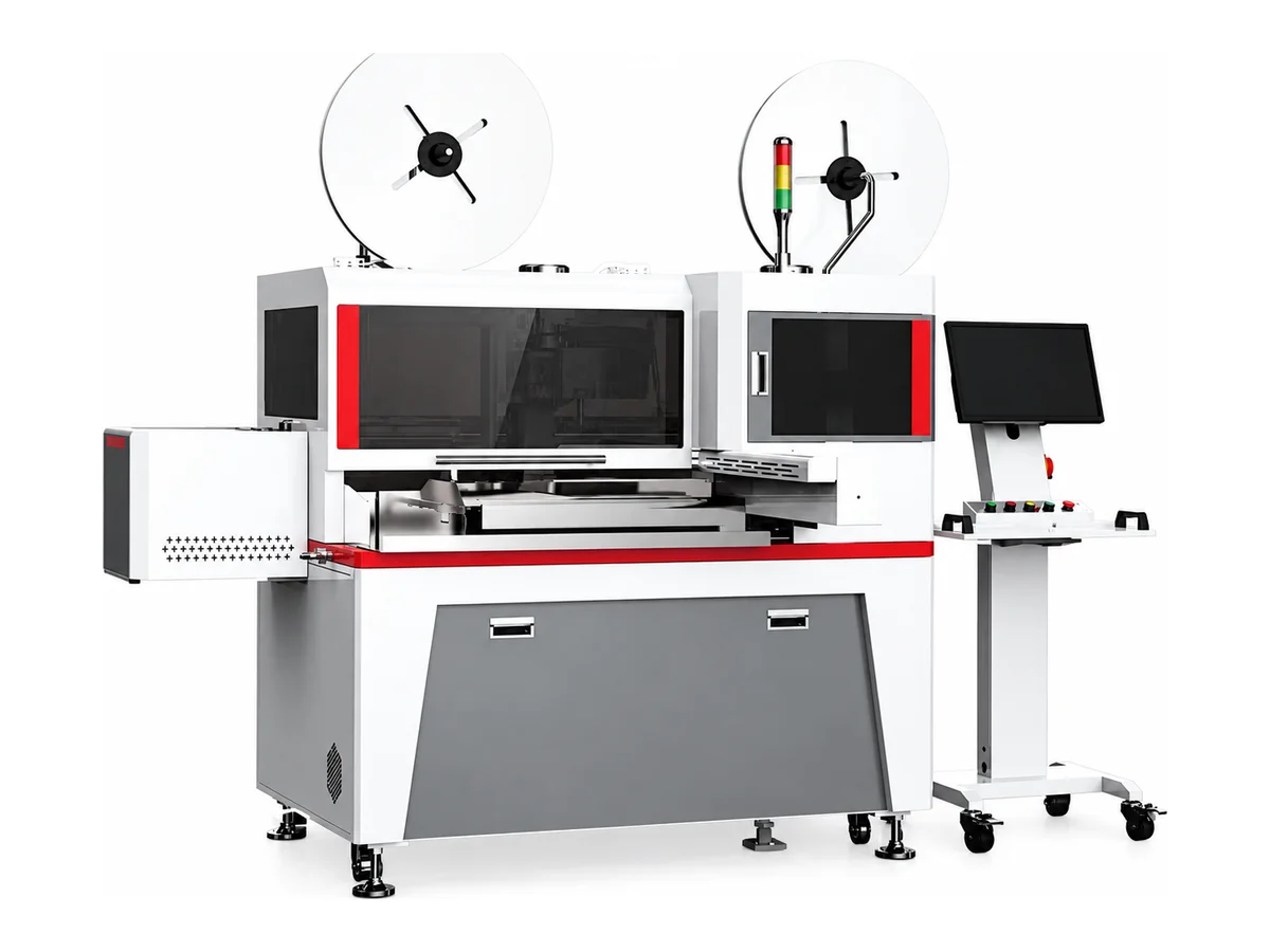
We combine wire cutting, stripping, single-end terminal crimping and housing insertion with twisting and tinning at the opposite end in the WM-3245. An eight-color wire selector supports harnesses assembled from different wire colors. The specified range is 0.5–2.5 mm² with insulation diameter up to 3.0 mm and standard cut lengths of 100–600 mm, matched to your applicator and connector.
Specifications
| Wire range | 0.5–2.5 mm²; maximum insulation outside diameter 3.0 mm |
|---|---|
| Process | Cut to length; full or partial stripping at both ends; single-end terminal crimping and housing insertion; opposite-end twisting and tinning; automatic cutting-depth and terminal crimp-position settings |
| Wire selection | Eight colors as standard |
| Cut length | 100–600 mm; customization available; minimum length depends on the applicator |
| Strip length | 0–8 mm |
| Tinning length | 0–8 mm |
| Crimping unit | 2 T servo terminal press |
| Cycle reference | 2.5 s/wire in the stated double-end crimping test at 50 mm wire length. Standard cut range is 100–600 mm; confirm the test configuration and your complete process cycle before ordering. |
| Motion control | Primarily Mitsubishi servo control |
| Material handling | Vibratory bowl feeding, internal wire reversing mechanism and servo-driven gripper wire feeding |
| Connector handling | Multilayer housing and mixed wire-length applications, with tooling matched to the connector; housing pull-back check |
| Monitoring | Wire presence, air pressure and housing presence; crimp-force and CCD vision monitoring optional |
| Output handling | Separate accepted and rejected output; accepted-parts conveyor |
| Data interface | MES production-data connection available |
| Electrical supply | Single-phase AC 207–242 V, 50/60 Hz, 40 A |
| Compressed air | 0.6 MPa |
| Dimensions | W2880 × D2000 × H1650 mm, excluding protruding parts |
| Weight | Approximately 700 kg |
| HS Code | 8463.90 (common reference — final classification confirmed by your customs broker) |
| Certification | CE (certificate provided with shipment) |
Key features
- Finish a connector end and a tinned tail in one workflow, reducing transfers between separate cutting, stripping, crimping, insertion and tinning stations.
- Select from eight wire colors to build a defined harness sequence. We match the wire lengths and cavity order to your drawing so the operator can check the first assembly against the pinout.
- Set stripping and tinning lengths up to 8 mm to suit the termination. We run your actual wire and review the tinned length, strand condition and insulation clearance before confirming the setup.
- Housing pull-back checks and separate accepted/rejected output support an organized inspection workflow. Optional CCD and crimp-force monitoring extend the checks for your terminal and housing combination.
- Send your wire, terminals, housings and pinout. We configure the applicator and insertion tooling, then record a sample run including the connector end and tinned tails for your review.
What it processes
- Connector-to-board harnesses with a terminated housing at one end and tinned wire tails at the other
- Multicolor internal equipment wiring with a repeatable cavity sequence
- Mixed-length or multilayer connector assemblies evaluated against actual housing samples
When tinning becomes the slowest step in harness preparation, the useful question is how much handling remains between processes. We bring the tin bath, wire preparation and connector-end assembly into one workflow. The sample run lets you review the finished tinned length and connector seating together, rather than approving each station in isolation.
For a harness with several colors or unequal wire lengths, the drawing must define which wire belongs in each cavity. We use that information to configure the wire selection and insertion sequence. Approve the first assembly against the pinout, then agree on the inspection and sampling plan for production.
If both ends need connector housings and wire seals, compare our WM-3247 double-end crimping and housing-insertion machine. For a dedicated tinning process, see our wire tinning and soldering machines.
Include your pinout, terminal and housing samples, wire specification, batch sizes and required tinned length in the inquiry. We will return a matched tooling proposal and a sample-run video for the complete process.
The gallery includes pneumatic crimp applicators that we configure and quote as options for the selected terminal. Harness examples show connector, wire and end preparation arrangements; we confirm the process and tooling for your exact assembly using your drawing and parts.
Engineering knowledge
Choose and troubleshoot this process
- Ferrule Crimping: Strip Length, Terminal Fit and Chain-Fed vs Loose-Fed MachinesCompare chain-fed and loose-ferrule crimping machines by wire preparation, changeover, terminal fit and batch output. Check WM-3243 and WM-3246 specifications.
- How to Choose a Terminal Crimping MachineChoose a terminal crimping machine by terminal presentation, wire range, applicator standard, required process steps, inspection method and production mix.
- Terminal Crimp Defects: Causes, Inspection and Corrective ActionsTroubleshoot low pull force, incorrect crimp height, strand loss, bellmouth defects, insulation support problems and inconsistent terminal feeding.
WM-3245 — common questions
What does this configuration make?
We configure this workstation for a crimped terminal inserted into a housing at one end and a twisted, tinned tail at the other. Wire cutting and stripping are integrated. Send the finished harness drawing so we can confirm the end processes and tooling together.
Is 2.5 seconds the complete harness cycle?
Use it as a test reference, not a finished-harness output guarantee. The specification describes a 2.5-second wire cycle for double-end crimping at 50 mm, while the standard cut range is 100–600 mm. We confirm that test configuration before ordering and time your required cutting, tinning, insertion and inspection sequence on samples.
How do you match the machine to my connector?
We need the terminal and housing part numbers, cavity layout, wire sizes, colors and finished lengths. These determine the crimp applicator, housing feed and insertion tooling. We check seating and the housing pull-back sequence on your actual parts; a wire-size range alone does not establish connector compatibility.
Are CCD and crimp-force monitoring included?
They are optional in this specification. Wire, air-pressure and housing-presence checks are listed, and the process includes a housing pull-back check. We list the selected monitoring functions and acceptance criteria on your quote.
Can it handle frequent product changes?
The eight-color selector supports different wire sequences, but a new terminal or housing can require different tooling and setup checks. Share your usual batch sizes and changes per shift. We base the recommendation on setup effort as well as machine running time.
Can you support the machine after delivery?
We set the voltage for your country and ship the English interface and manual. For replacement blades, gripping parts and applicator wear parts, every quote lists them with unit price and the location they ship from. The delivered electrical configuration is confirmed on the quote against the listed supply requirement.
Related machines in Crimping & Connector Assembly
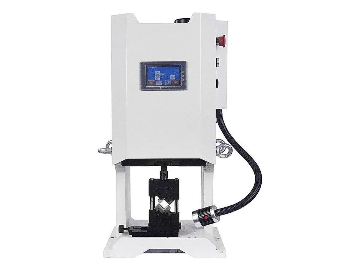
10-Ton Servo Terminal Crimping Machine, 100 kN Bench Press
Model WM-3110T
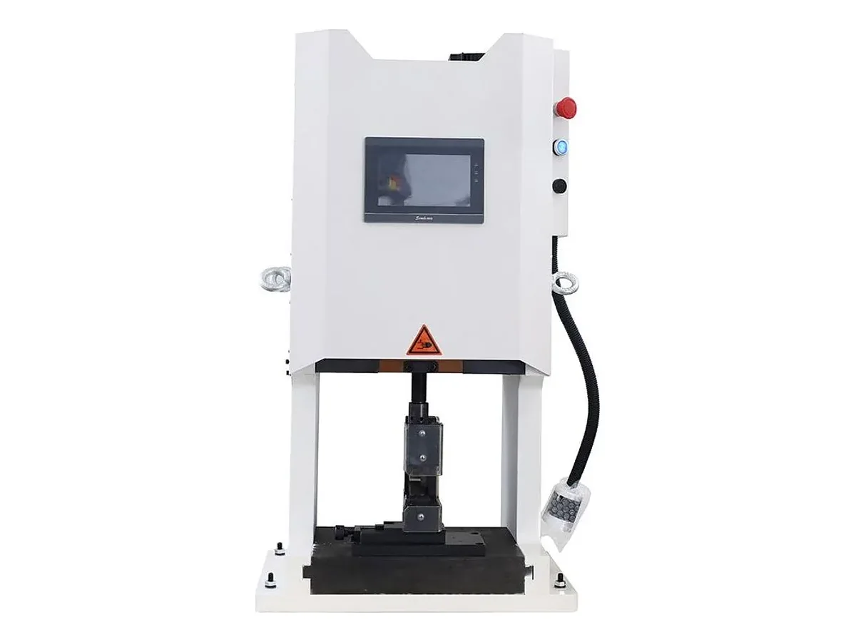
20-Ton Servo Cable Lug Crimping Machine, 200 kN and 40 mm Stroke
Model WM-3120T
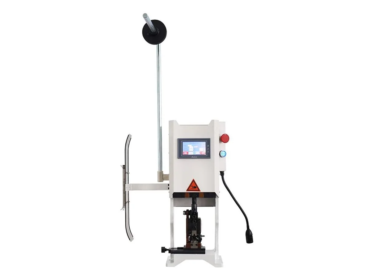
2-Ton Servo Terminal Crimping Machine, 20 kN Touchscreen Bench Press
Model WM-3102S