CNC Busbar Punching, Shearing and Bending Machine with Three Workstations WM-9400
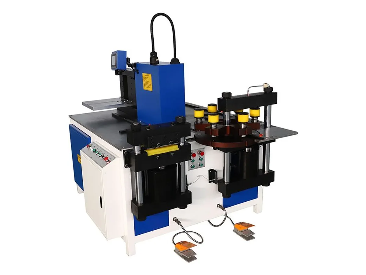
Our WM-9400 combines hydraulic punching, shearing and CNC-controlled bending in one hand-loaded busbar processing machine. Choose a 160, 260 or 300 mm capacity configuration for your copper busbar drawings. The configurations have different station forces, thickness limits and motor power; the 160 mm configuration shears up to 12 mm thickness, while the 260 and 300 mm configurations specify 16 and 20 mm respectively.
Specifications
| Processes | Busbar punching, shearing and bending; workpieces loaded and repositioned by the operator |
|---|---|
| Capacity configurations | 160 mm / 260 mm / 300 mm; specifications below follow this order |
| Punching force | 350 / 500 / 800 kN |
| Punch diameter range | 160 mm configuration: Ø4.3–32 mm; 260 mm: confirmed on the quote; 300 mm: Ø4.3–25 mm |
| Punching width and thickness limits | 160 mm configuration: width 160 mm, thickness 16 mm; 260 mm: confirmed on the quote; 300 mm: width 300 mm, thickness 20 mm |
| Shearing force | 400 / 800 / 1000 kN |
| Maximum shearing size (width × thickness) | 160 × 12 / 260 × 16 / 300 × 20 mm |
| Bending force | 350 / 500 / 800 kN |
| Flat-bending limits | 160 mm configuration: width 160 mm, thickness 16 mm; 260 mm: 260 × 16 mm; 300 mm: width 300 mm, thickness 20 mm |
| Edgewise bending | 160 mm configuration: width 30–100 mm; 260 mm: maximum 120 × 12 mm; 300 mm: width 30–100 mm |
| Minimum U-bend width | 160 and 300 mm configurations: 50 mm; 260 mm: confirmed on the quote |
| Main motor power | 3 × 4 / 3 × 5.5 / 3 × 7.5 kW |
| Control | PLC, encoder and touch screen |
| Dimensions | 1750 × 1350 × 1300 / 1800 × 1500 × 1300 / 1950 × 1550 × 1200 mm |
| Machine weight | 1.5 / 1.8 / 1.9 t |
| Certification | CE (certificate provided with shipment) |
Key features
- Keep cutting, hole making and bending at one machine, with separate workstations for moving a busbar through its preparation sequence.
- Select the capacity configuration against the most demanding operation on your drawing, rather than choosing by busbar width alone.
- The rotary punch tool holder brings installed tools into position for different holes; we match punch and die sizes to your hole pattern and material thickness.
- PLC, encoder and touch-screen control support bend setup while the operator supports and repositions the workpiece.
- Send your drawing and copper samples for a recorded trial showing hole shape, cut edge, bend geometry and the finished connection.
What it processes
- Copper busbar preparation for switchgear and electrical distribution cabinets
- Punched connection holes and formed offsets in copper bars
- Flat bends, edgewise bends and U-shaped connections with matched tooling
Choose the configuration by operation
Our WM-9400 family puts a punching head, shear and bending station on one machine. The operator presents the bar to each station and supports it through the working cycle. Use the comparison below to choose a starting configuration, then send the complete drawing so we can check tooling and clearance around existing bends.
All bar sizes below are width × thickness, not cable cross-sectional area. Where width and thickness are specified as separate maxima, we confirm the combined working size for your material grade and operation on the quote.
| Specification | 160 mm configuration | 260 mm configuration | 300 mm configuration |
|---|---|---|---|
| Punching force | 350 kN | 500 kN | 800 kN |
| Punch diameter range | Ø4.3–32 mm | Confirmed on the quote | Ø4.3–25 mm |
| Punching width limit | 160 mm | Confirmed on the quote | 300 mm |
| Punching thickness limit | 16 mm | Confirmed on the quote | 20 mm |
| Shearing force | 400 kN | 800 kN | 1000 kN |
| Maximum shearing size | 160 × 12 mm | 260 × 16 mm | 300 × 20 mm |
| Bending force | 350 kN | 500 kN | 800 kN |
| Flat bending | Width 160 mm; thickness 16 mm | Maximum 260 × 16 mm | Width 300 mm; thickness 20 mm |
| Edgewise bending | Width 30–100 mm | Maximum 120 × 12 mm | Width 30–100 mm |
| Minimum U-bend width | 50 mm | Confirmed on the quote | 50 mm |
| Main motor power | 3 × 4 kW | 3 × 5.5 kW | 3 × 7.5 kW |
| Machine dimensions | 1750 × 1350 × 1300 mm | 1800 × 1500 × 1300 mm | 1950 × 1550 × 1200 mm |
| Machine weight | 1.5 t | 1.8 t | 1.9 t |
The 160 mm configuration’s 12 mm shear limit is different from its 16 mm punching and flat-bending thickness limits. The 300 mm configuration’s greater station force also does not change its specified Ø25 mm maximum punch diameter. We check these limits against each operation on your drawing before selecting the tooling.
Watch the process and the finished copper
The video brings together three family demonstrations: hole punching, end-corner rounding and bending. Each sequence includes the resulting copper part. The corner-rounding tool is a configuration item to confirm on the quote; it is not a separate shearing-capacity test. The photographs show representative machine layouts, the working punch head and formed copper samples. We confirm the layout and tool set for your selected configuration.
For your trial, we agree the hole positions, cut-edge condition, bend dimensions and surface requirements, then film the actual material being processed. Throughput includes manual handling and movement between stations, so the edited demonstration does not establish a production rate.
Prepare the machine for your parts
Send a dimensioned drawing with material grade, width, thickness, hole pattern, bend radii and production quantity. Include the full part outline: a short distance between bends or a formed section near the next operation can change the required tool and support.
We set the voltage for your country and ship the English interface and manual. Electrical supply, hydraulic-oil requirements, included dies and any corner-rounding or embossing tools are confirmed on the quote. For wear items, every quote lists them with unit price and the location they ship from.
If you need to remove an insulating sleeve before making a connection, review the WM-195 flexible copper busbar peeling machine alongside this busbar processing category.
Engineering knowledge
Choose and troubleshoot this process
- Busbar Machine Sample Trial and Acceptance ChecklistPrepare a busbar machine trial with material identification, drawing tolerances, hole and bend measurements, complete-cycle timing and a documented acceptance record.
- Busbar Punching, Shearing and Bending Defects: What to CheckTroubleshoot copper busbar burrs, hole-position errors, bend springback and surface marks with a controlled inspection sequence and drawing-based acceptance.
- How to Choose a Busbar Punching, Shearing and Bending MachineChoose a copper busbar machine by operation-specific capacity, hole tooling, bend geometry and handling. Compare WM-9400 configurations and plan a sample trial.
WM-9400 — common questions
Are the three capacity configurations the same specification?
No. They share the three-workstation process, but station forces, motor power, dimensions and processing limits differ. The 160 mm configuration specifies 160 × 12 mm shearing, the 260 mm configuration 260 × 16 mm, and the 300 mm configuration 300 × 20 mm. We identify the selected configuration and tooling on your quote.
Can the 160 mm configuration shear 16 mm thick busbar?
Its stated shearing limit is 12 mm thickness. The 16 mm figure belongs to its punching and flat-bending thickness limits. For thicker shear work, review the 260 or 300 mm configuration with us using your material grade and part drawing.
Does the largest configuration make the largest holes?
The specified punch diameter range is Ø4.3–32 mm for the 160 mm configuration and Ø4.3–25 mm for the 300 mm configuration. The 260 mm configuration's hole range is confirmed on the quote. Hole diameter, material thickness and tooling must be checked together; higher station force does not by itself establish a larger hole range.
Does CNC mean the busbar feeds automatically?
The operator loads, supports and repositions the busbar between operations. CNC-controlled bending does not mean an automatic loading, feeding or transfer line. Tell us your part sequence and target output so we can demonstrate the required working cycle.
What does the demonstration video show?
It shows this machine family's punching, end-corner rounding and bending processes, followed by views of the processed copper. Corner-rounding tooling is confirmed on the quote. The video demonstrates the operations; it is not a maximum-capacity or accuracy test for every configuration. We record a trial for your selected configuration and samples before you order.
Does this machine remove busbar insulation?
For insulation sleeve removal from flexible copper connections, see our WM-195 busbar peeling machine. The WM-9400 processes the bar itself by punching, shearing and bending.
What information do you need to recommend a configuration?
Send the material grade, busbar width and thickness, hole diameters and positions, bend drawing and target output. Include edgewise bends, minimum distances between bends and any finished-surface requirements. Leave your email and our engineering and sales team will contact you within 12 hours with a quotation proposal.